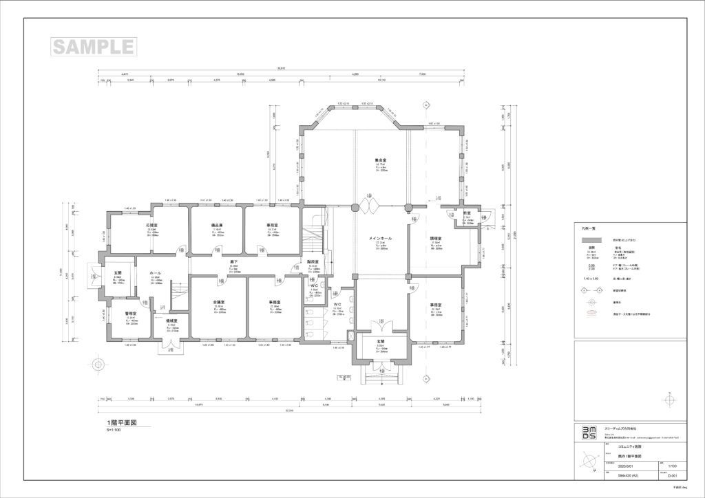
2D Blueprints
Based on the captured 3D laserscan data (point clouds), we can create 2D floor plans, sections, and views in CAD. For this purpose, the point clouds are imported into the CAD software and meticulously drawn by our trained team. Depending on the client’s requirements, we can create a simple 1:100 plan for, e.g., space management, a 1:50 foundation for planning, or a deformation-accurate documentation for analysis and planning. We offer three basic variants, which can, however, be expanded at any time according to the client’s specifications.
1. Basic Variant (Scale 1:100)
Basic Variant 1 is a straightforward plan for space management or facility management. The drawing accuracy is not deformation-accurate and is 20 mm precise.
The basic components are represented:
Walls
- Columns
- Stairs
- Windows
- Doors
- Sanitary fixtures
- Built-in furniture
For the drawn components, additional height measurements, information elements for rooms, doors, and windows, as well as exterior dimensions of the rooms are created. The information elements have the following attributes:
Room
- Room number
- Room use
- Usage area
- Room perimeter
- Clear room height
Door
- Clear width
- Clear height
Window
- Clear width
- Clear height
All information elements can be customized or expanded according to the client’s individual requirements.

2. Basic Variant (Scale 1:50)
Basic Variant 2 is an extension of Basic Variant 1 and is suitable, at a scale of 1:50, as a basis for planning. The drawing accuracy is not deformation-accurate and is 20 mm precise. Compared to Basic Variant 1, it includes the following:
- Wall thickness
- Dimensions of columns
- Roof structure
- Stair labeling (tread/rise)
- Stair strings
- Stair undercuts
- Railings
- Window subdivisions + frames
- Door frames
- Door thresholds
- Projected components (beams, ceiling offsets)
- Component labeling
In addition to the drawn components, the upper edge of the finished floor (FFB) and the lower edge of the finished ceiling (FD) are added in each room, along with information elements for rooms, doors, and windows, as well as exterior and interior dimensions of the rooms and openings. The information elements have the following attributes:
Room
- Room number
- Room use
- Usage area
- Room perimeter
- Clear room height
- Floor covering
Door
- Clear width
- Clear height
- Door leaf material
- Opening direction
- Door type
- Door glass
- Fire protection class
Window
- Clear width
- Clear height
- Sill height
- Bottom of lintel
- Window type
- Opening type
All information elements can be customized or expanded according to the client’s individual requirements.

3. Basic Variant (Scale 1:50)
Basic Variant 3, at a scale of 1:50, is suitable as a basis for planning and can also be used, with a deformation-accurate representation, as documentation of the building structure. Additionally, subsections can be created at scales of 1:20 and 1:10. Compared to Basic Variant 2, it includes the following:
- Deformed components (walls, columns, structure, etc.)
- Ceiling reflections
- Facade decorations
- Depiction of cracks and joints
In addition to the drawn components, the upper edge of the finished floor (FFB) and the lower edge of the finished ceiling (FD) are added in each room, along with information elements for rooms, doors, and windows, as well as exterior and interior dimensions of the rooms and openings. The information elements have the following attributes:
Room
- Room number
- Room use
- Usage area
- Room perimeter
- Clear room height
- Floor covering
Door
- Clear width
- Clear height
- Door leaf material
- Opening direction
- Door type
- Door glass
- Fire protection class
Window
- Clear width
- Clear height
- Sill height
- Bottom of lintel
- Window type
All information elements can be customized or expanded according to the client’s individual requirements.


